#Servo motor arduino diagram how to
Here is How To Create Arduino MAX 7219 CNG Basic Circuit to Control LED, 7 Segment Displays in Own Custom Ways Rather Than Using Modules.Īdditionally, performing a search on this website can help you.

Arduino Door Bell With Push Button With 3 LED.Choosing The Correct LCD Display For Arduino Like BoardsĬhoosing The Correct LCD Display For Arduino Like Boards Is Crucial For Budget, For Compatibility With Wider Range Of Board & Microcontroller.Here is Detailed Arduino 7 Segment LED Display Tutorial For the Beginners With Example Codes, Circuit Diagram Which Uses TM1637, Has 4 Digit.
#Servo motor arduino diagram driver
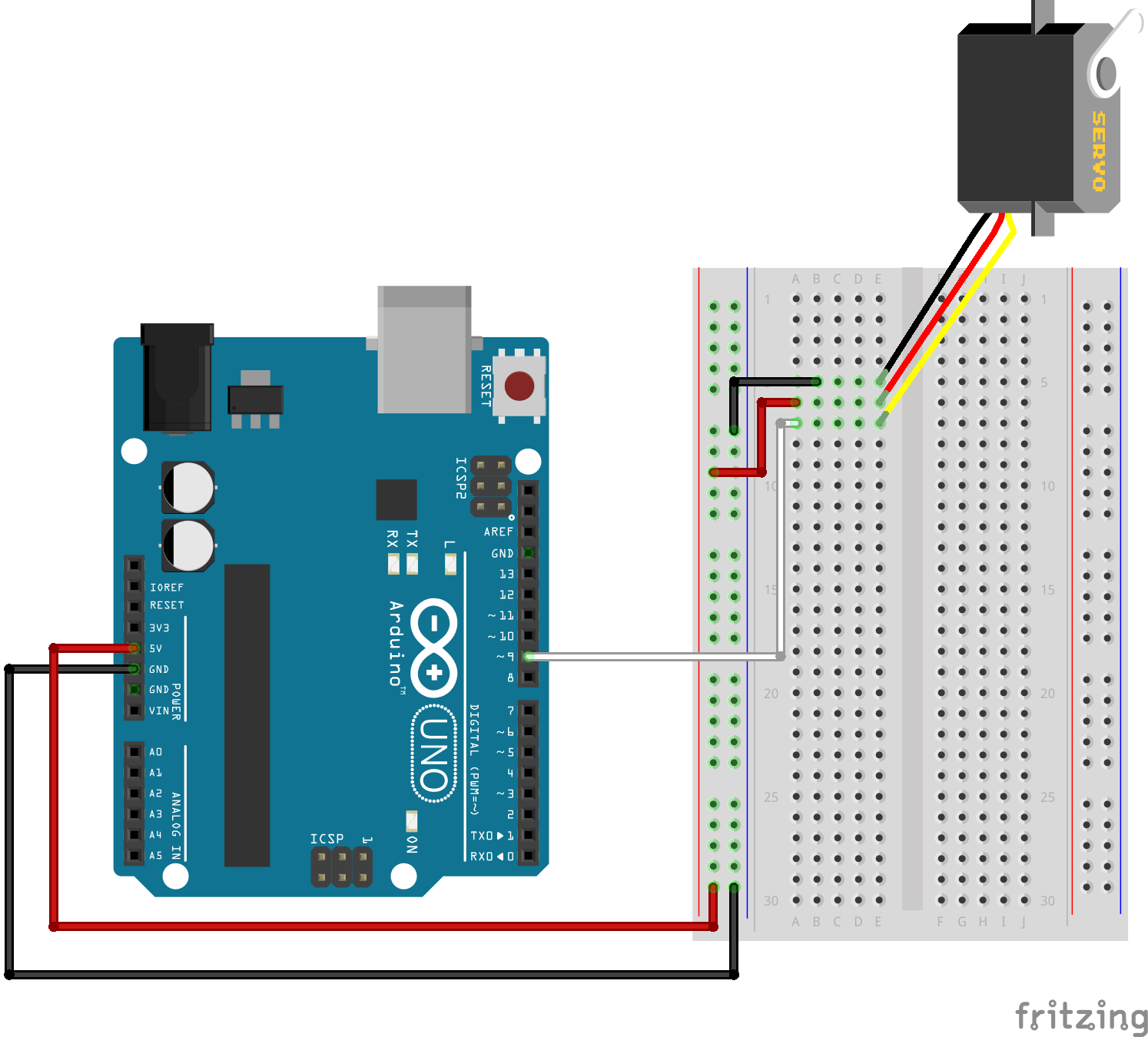
Arduino 7 Segment LED Display Tutorial (TM1637 4 Digit) Figure b 4 schematic of servo motor wired to the arduino board scientific diagram driver circuit controller or electrical4u how control motors with 3 examples ac working principle construction characteristics applications electricalworkbook an rc using 555 ic technology servomotor aprenndo gadgetronicx mini mega in main.Tagged With controlling servo with arduino and switch, button operated motor program arduino, arduino servo button code, arduino servo push button, arduino push button code, arduino servo with one push button code, arduino push button servo control, arduino nano servo sweep button, arduino control servo with push button, arduino servo motor codes with buttonsĪrticles Related to Arduino Servo Motor Control With Pushbutton That kind of usage is for making a mechanical knob digitally controlled with timer. When timer will end the servo will sweep. The best thing about servo motors is that they can be directly connected to an Arduino, Connect the motor to the Arduino in the manner shown in the table below: Servo red wire 5V pin Arduino. The following two paragraphs will help you identify the right type of servo motor for your project/system. There are lots of servo motors available in the market and each one has its own speciality and applications. When you will push the button, the green light will be off and yellow will momentarily on, then red light will be on and timer will start. MG90S Metal Gear, MG995 High Torque Metal Gear, VTS-08A Analog Servo. Similar setup like Idea 1 but normally there will be green light. In this tutorial, an Arduino board will be used to power and control a small servo motor. That kind of usage is normal safety precaution for industrial tools. At the end of swap, again red light will be off and green light will be on. Also the timer will start and servo motor will start to sweep. When you will push the button, the green light will be off and yellow will momentarily on, then red light will be on. Hence we can get rotation from servo motor while we vary resistor value.Previously we have shown you how to perform multitasking in Arduino Traffic Light With LED Display Timer With Push Button Switch.Ĭan you modify the project yourself so that normally there will be green light. Range of variable resistor is converted into digital value and the corresponding pulse width modulation (PWM) pulse is given to servo motor through digital pin D9. In this project variable resistor connected with analog input pin A0 and the servo motor pulse pin connected with digital pin D9, this pin can give pwm pulse. Here the rotation of variable resistor imitate by the rotation of servo motor.(A servo is a rotary actuator) The connections for the joystick module and the Arduino are as follows. First, connect the joystick module with the Arduino. Same goes for LCD displays, and many other components. The hardware part of this project is very easy to make. Connect the PWM signal pin of the servo motor with the 9the pin of Arduino. Give 5v voltage supply to the servo motor via the voltage pin. Instead, you add a 2-pin header where you solder the VCC and GND leads on. Connect the ground pin of the servo motor with the 10th pin of IC. Same thing for power supplies, they dont get included. The servo motors are used in many applications, this motor works with input pulse and rotation depends on input pulse duration. If the servo uses 3 wires, then add a 3-pin header.


 0 kommentar(er)
